


| Home | People | Research | Projects | Teaching | Theses | Downloads | Links | Contacts |  |
 |

|
 |
|||||||||||||

|
||||||||||||||
|
||||||||||||||
 |
Research
|
|||||||||
|
Machine visionMore applications can be seen by our laboratoriesMeasurements of vehicle trajectory using 3D stereoscopyOUTLINE
Nowadays, stereo vision techniques are broadening to a wide range of applications.
They provide a 3D representation of the real world scene captured by a couple of cameras, from which a
large amount of information can be inferred.
Characterizing object's trajectory, whether they are vehicles or people, finds a useful
application in event detection, traffic monitoring and video-surveillance. Furthermore, the estimation of
positioning and aligning parameters of a target object is widely employed in machine vision as well as
in industrial automotive applications.
METHOD
We devised a stereo-based, markerless and non-invasive approach, capable to appreciate deviations in
motion direction of even tenths of degrees.
Usually, in order to manage measuring the vehicle alignment with a high accuracy, it needs to be performed when the vehicle
is still, on the testing platform.
Our approach joints photogrammetry and videogrammetry principles by gathering all the data coming from the vehicle
while approaching
the test apparatus, by analyzing the tangent to its trajectory tracked and recovered using 3D stereo [MV1][MV2].
To measure the longitudinal deviation of the vehicle trajectory using stereo tracking in real time, using
a low power architecture, it is suitable to track a region of the vehicle that is integral with the vehicle itself.
To this purpose, we have chosen a natural target always present in the vehicles, i.e. the license plate, a textured
region always offering a high number of features to be tracked.
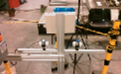
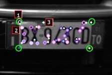
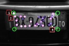
Fig. 2: From left to right: the stereo couple; the features detected by our algorithm in the left and right image of the stereo couple. For instance, features 1 and 2 match, while 3 and 4 do not. Since this algorithm works at 25 frame per second (fps), the vehicle's trajectory can be approximated by its instant tangets, using RANSAC to filer each of the three vectors components. These vectors can be thus projected onto the floor reference plane and the vehicle’s trajectory can be built incrementally, until the vehicle stops.RESULTS
The accuracy of our algorithm has been first assessed using a license plate mounted on a mechanical support free
of moving with controlled velocity along a rigid linear guide (Fig. 3, first stereo pair, from left to right).
The guide is placed at the ground level
and the deviation angle with respect to a line used as a reference (0° angle) to the sistem can be varied and
measured with an accuracy of 0.02°. This yields a perfectly linear trajectory with its tangents coinciding
with the trajectory itself.
Fig. 3: From left to right: left (a) and right (b) rectified pair of images of the license plate moving along a known trajectory; left (c) and right (d) pair of images of the vehicle moving toward the stereo rig, with the "sand track" deposited on the floor. In order to establish a ground truth even in real conditions, a track of the car trajectory has been obtained by fixing to the vehicle a rigid case releasing sand to draw a colored track (the sand track) deposited on the floor (the second stereo pair of Fig. 3). The sand track is processed with an accuracy of 0.05° and acts as a ground truth line.In Fig. 4, left, the angular error versus the ground-truth deviation angle for 14 test sequences is shown. 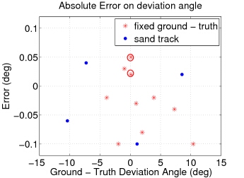
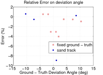
Fig. 4: The absolute (left) and relative (right) angular error (in degrees) The measures have been achieved by averaging the values in the last three meters, since we are mostly interested to the last value, when the vehicle stops. In this plot, 10 sequences have been collected using the mechanical guide validation method, whereas 4 more sequences have been achieved through the sand track method. Most of the trials (9 out of 14) using fixed ground truth have been accomplished for small variations of 5° in absolute value. This is because in this application we are interested to study small angles with the highest accuracy, supposing that while approaching the test system the vehicle is already somehow aligned ([-15°,+15°]). As it can be seen, the system proves to be very accurate. In fact, the absolute angular error is less than 0.1°, comparable with the accuracy of the calibration procedure of the stereo rig. Fig. 4, right, shows that the percentage errors, keep under 10%, independently of the deviation angle (the near-zero measures circled in the left image have been left out of consideration), thus proving that our method is reliable in all the range of interest. More details are reported in [MV3]. Acknowledgements Measurements of geometric properties of a vehicle beam's light profile(also, see here) |
||||||||
Copyright © 2008, A.G. - All Rights Reserved
|